The Losmandy Porta-Jib takes approximately 10-20 minutes to set up and can be done by one person, but for safety we recommend two people if you are not familiar with it.
Assembly is done in three sections - the dolly base, the tripod and the jib main assembly. Once assembled, the jib needs to be balanced prior to using it. We cover all of these steps below.

Assembling the Losmandy Porta-Jib
1. Assemble The Dolly Base
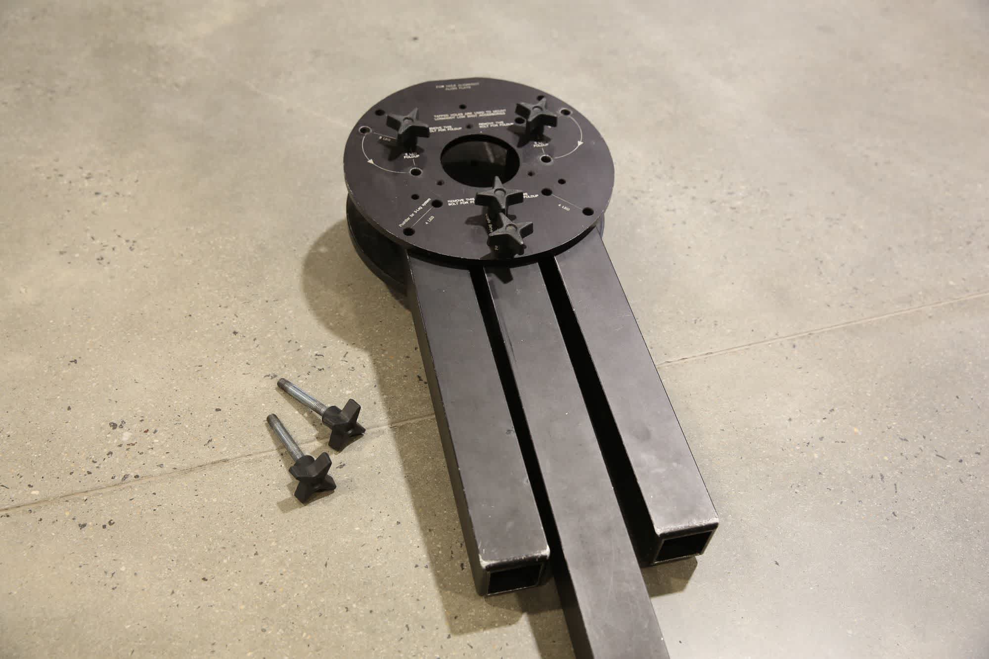
We will start by setting up the spider dolly. Remove the dolly base from the case and slightly loosen all the screws.
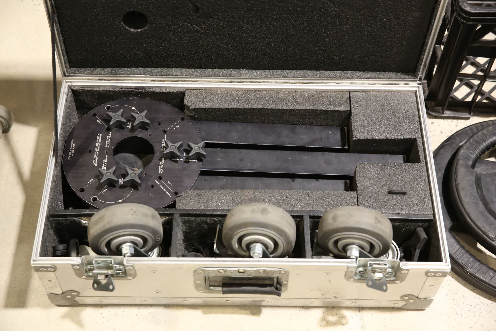
The spider dolly packed in its transport case.
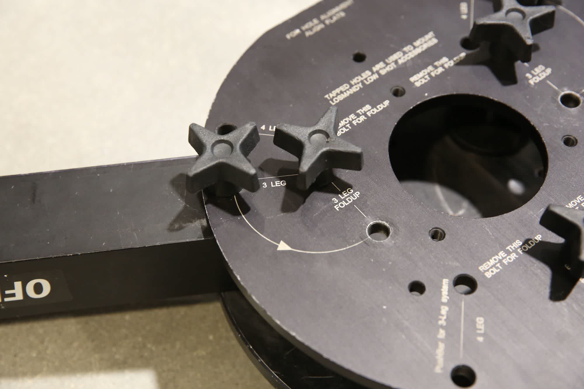
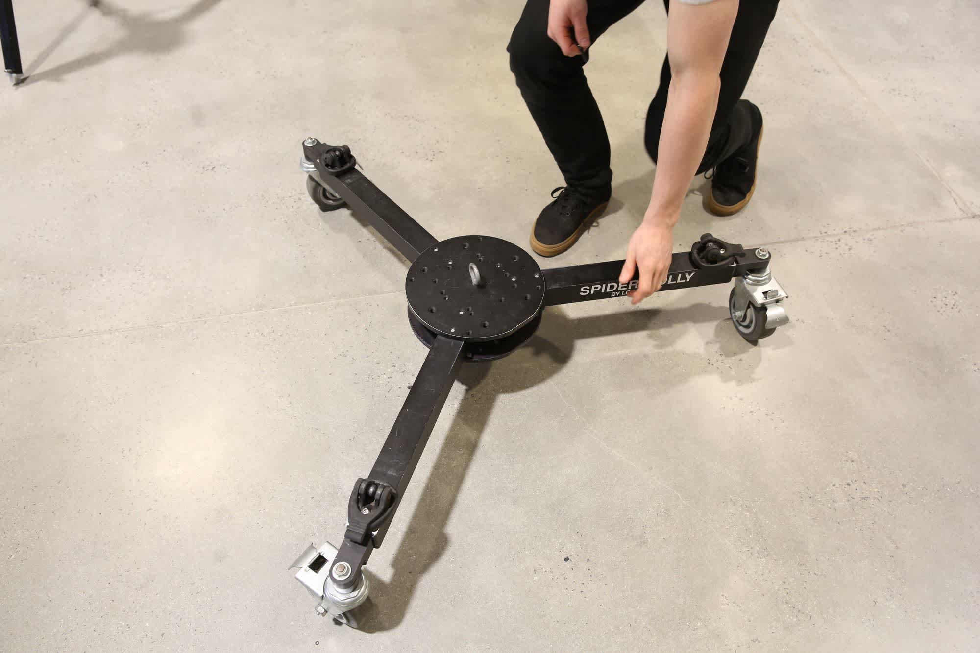
Remove the two screws that allow the two outer legs to swivel out, and move them out to the 3 leg position (as indicated by the markings on the dolly base). Reinstall these two screws, then tighten all other screws and flip the entire thing over.
Removing two screws and loosening the others allows the two outer legs to be opened to their production position.
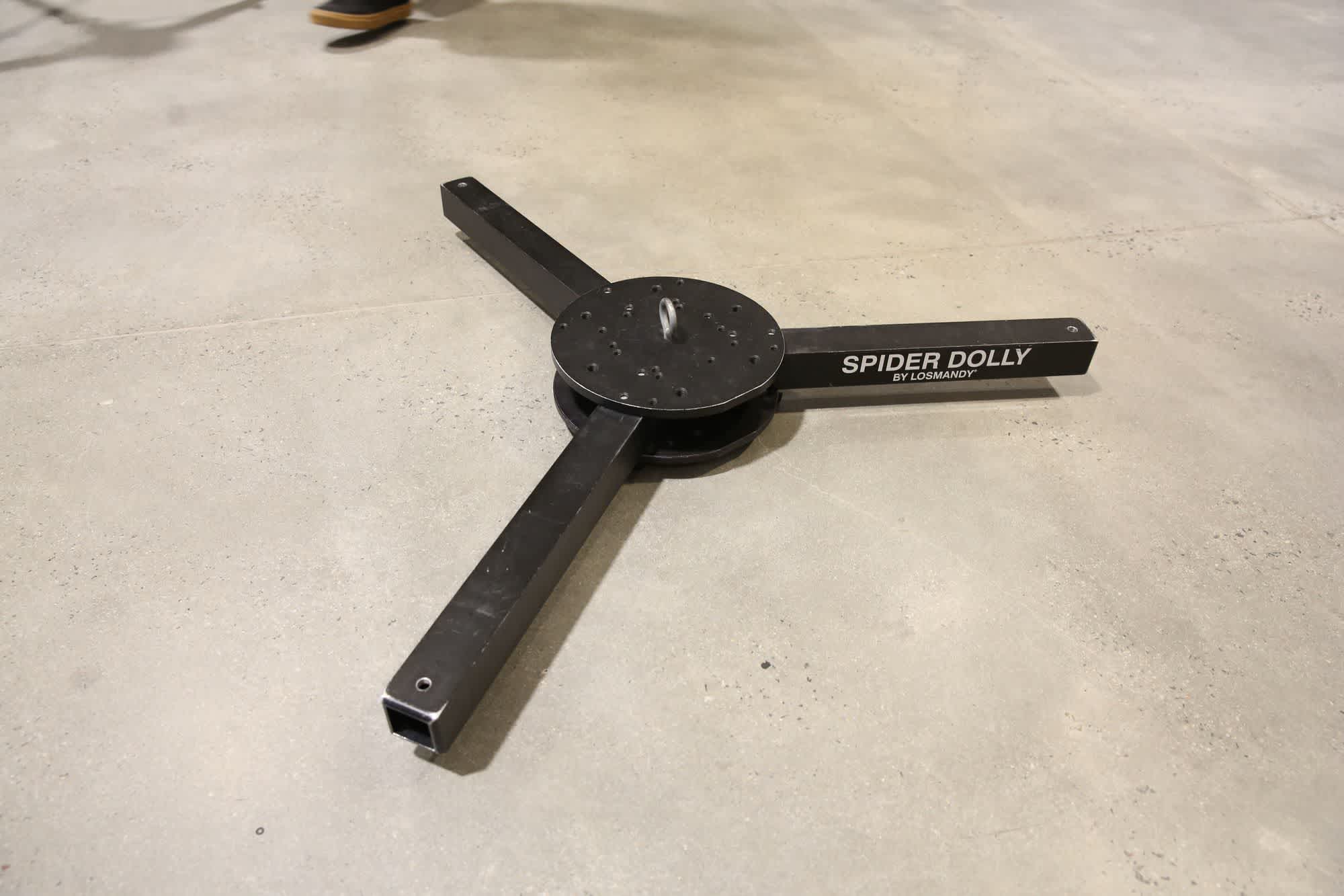
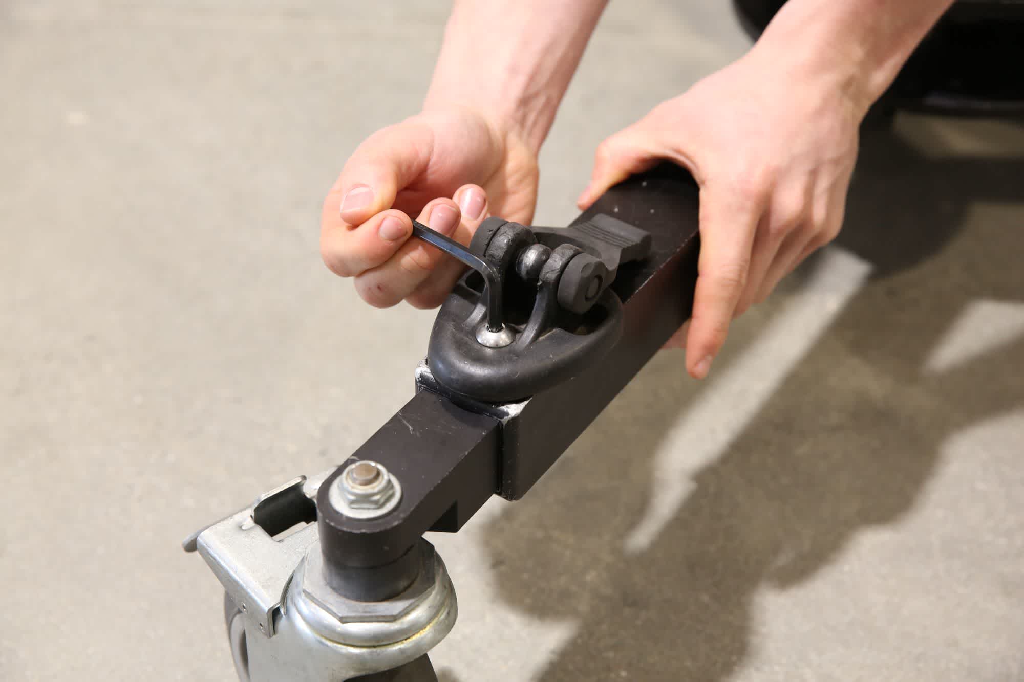
Install a wheel into the end of each tube and use the bolt-down feet to attach securely. Do this for all 3 wheels.
The wheels are secured to the dolly by bolting down each tripod foot.
2. Attach The Tripod To The Dolly
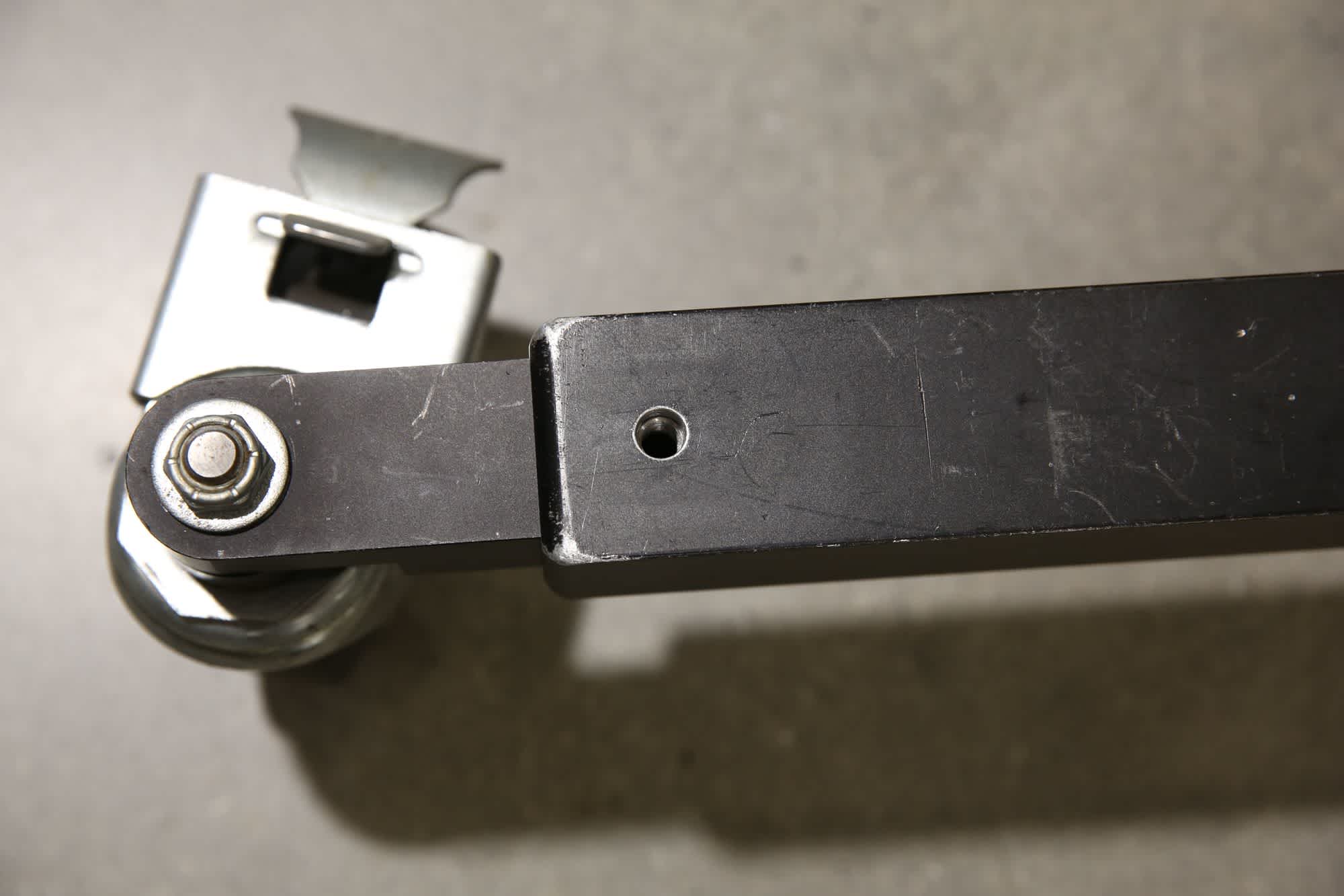
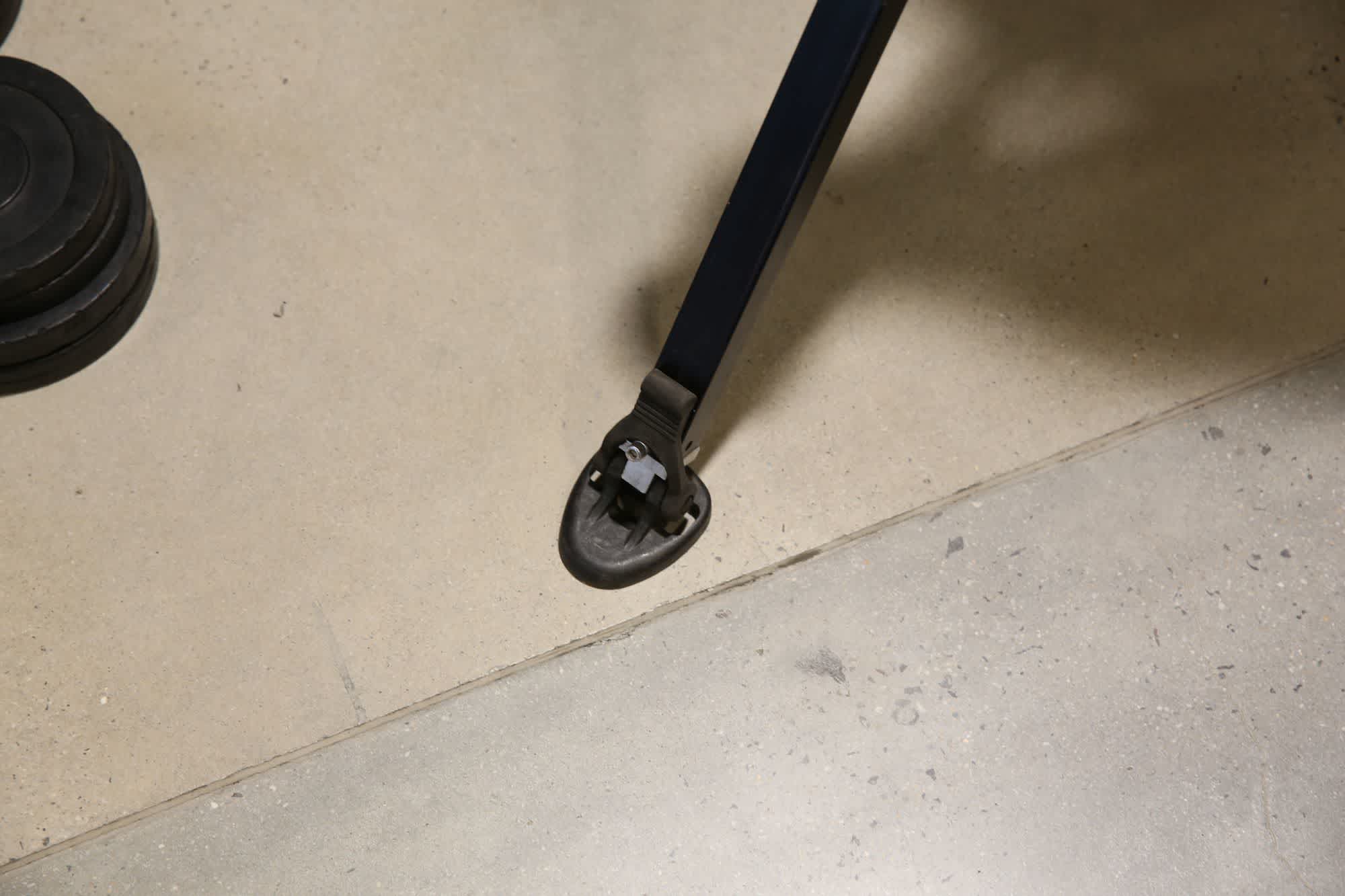
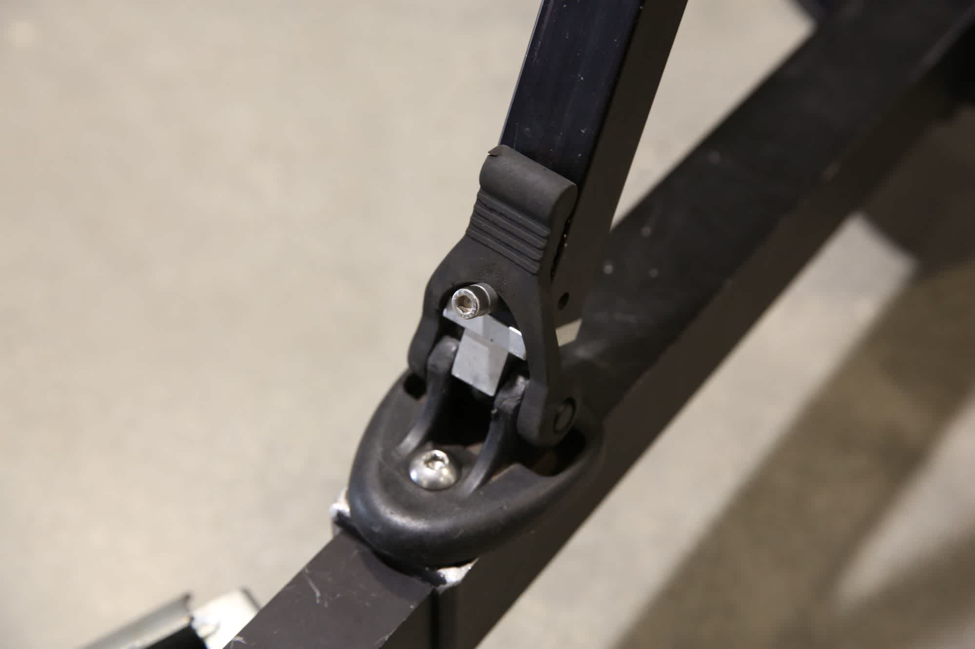
Remove the ground feet from the tripod and raise the tripod approximately 50cm. Place the tripod onto the spider dolly - each leg sits in one of the feet you attached in the previous step. Secure the tripod using the rubber fasteners on the feet.
Each leg of the tripod sits in a foot attached in the previous step and is secured with the lift-over rubber fastener.
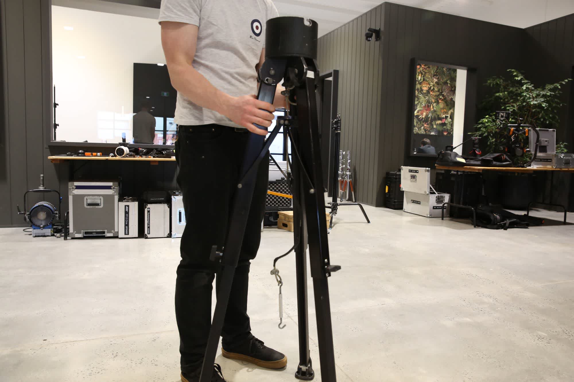
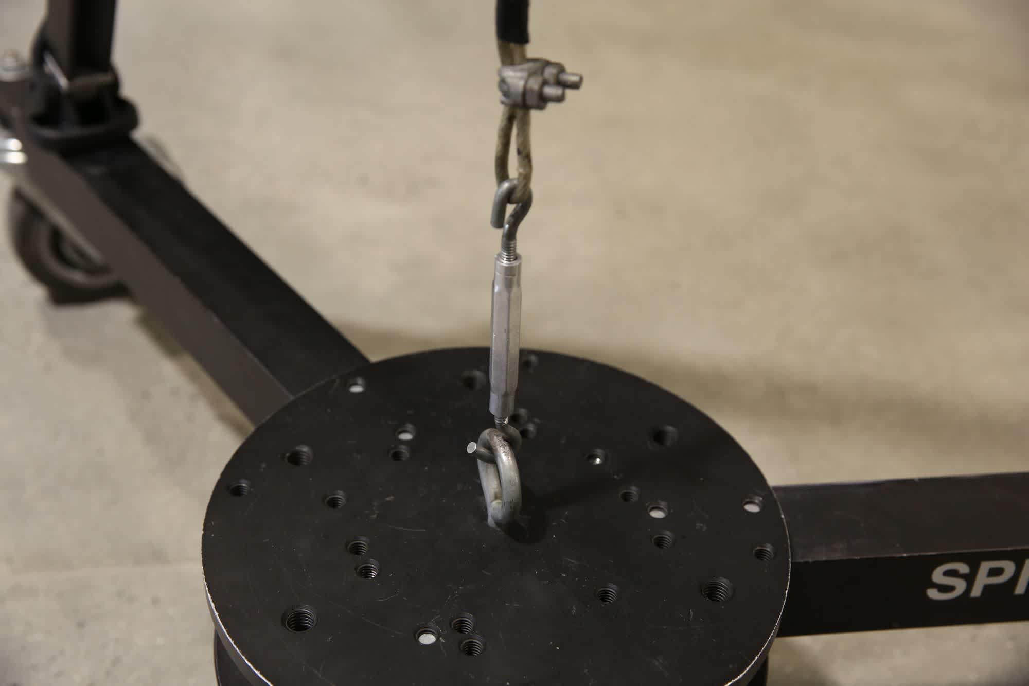
Extend the turnbuckle to its maximum length and hook it into the eye bolt on the spider dolly base. Raise the legs up on the tripod so that they take up slack on the cable. Ensure the tripod is level using the bubble level located in the top of the tripod. Once level, tighten down the leg locks at the top of the tripod.
Once the slack is taken out of the cable you can tighten down the turnbuckle. This is a safety cable that prevents the tripod coming off the spider dolly.
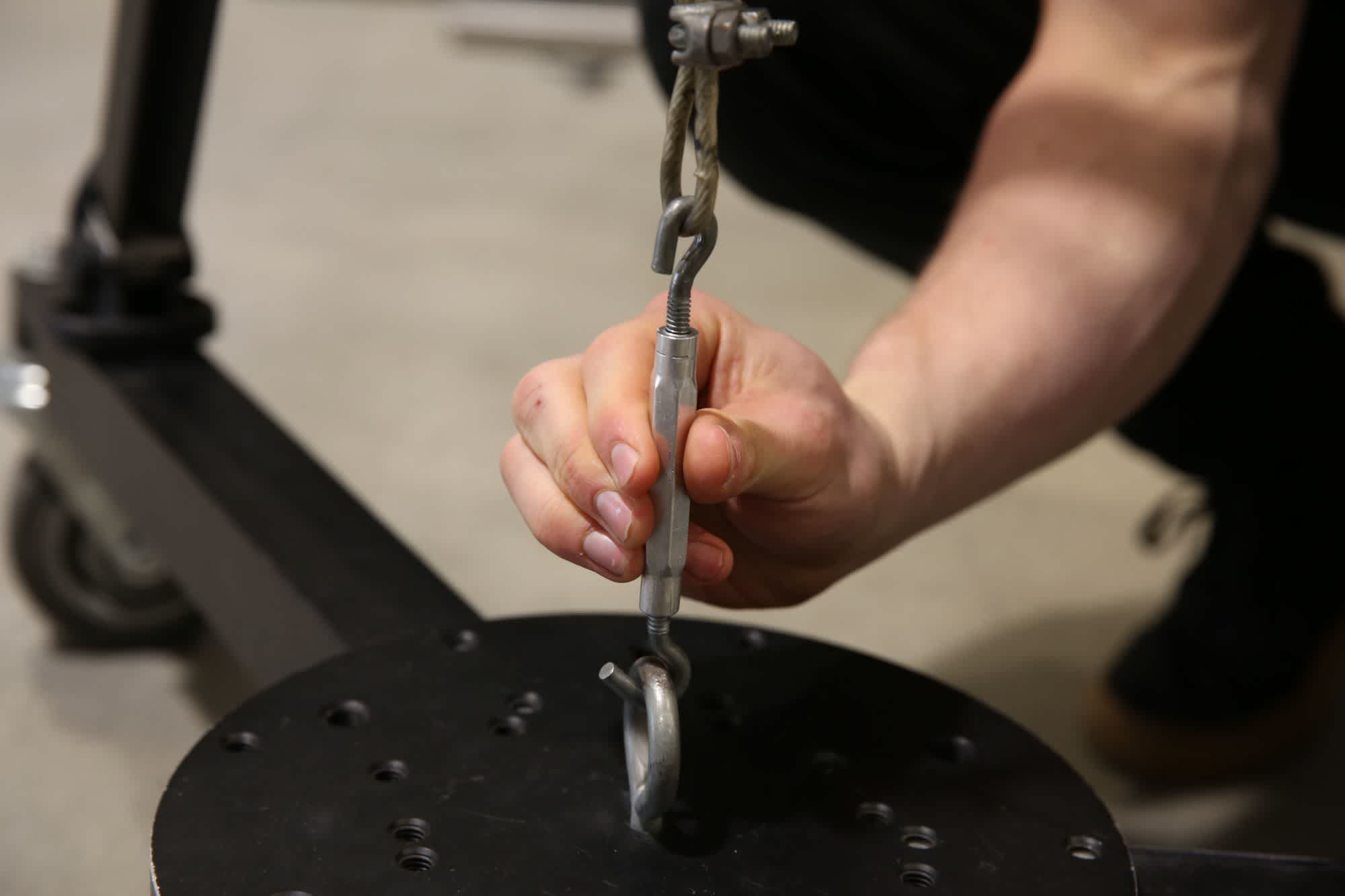
Tighten the turnbuckle to secure the tripod to the dolly.
3. Install The Jib Main Assembly
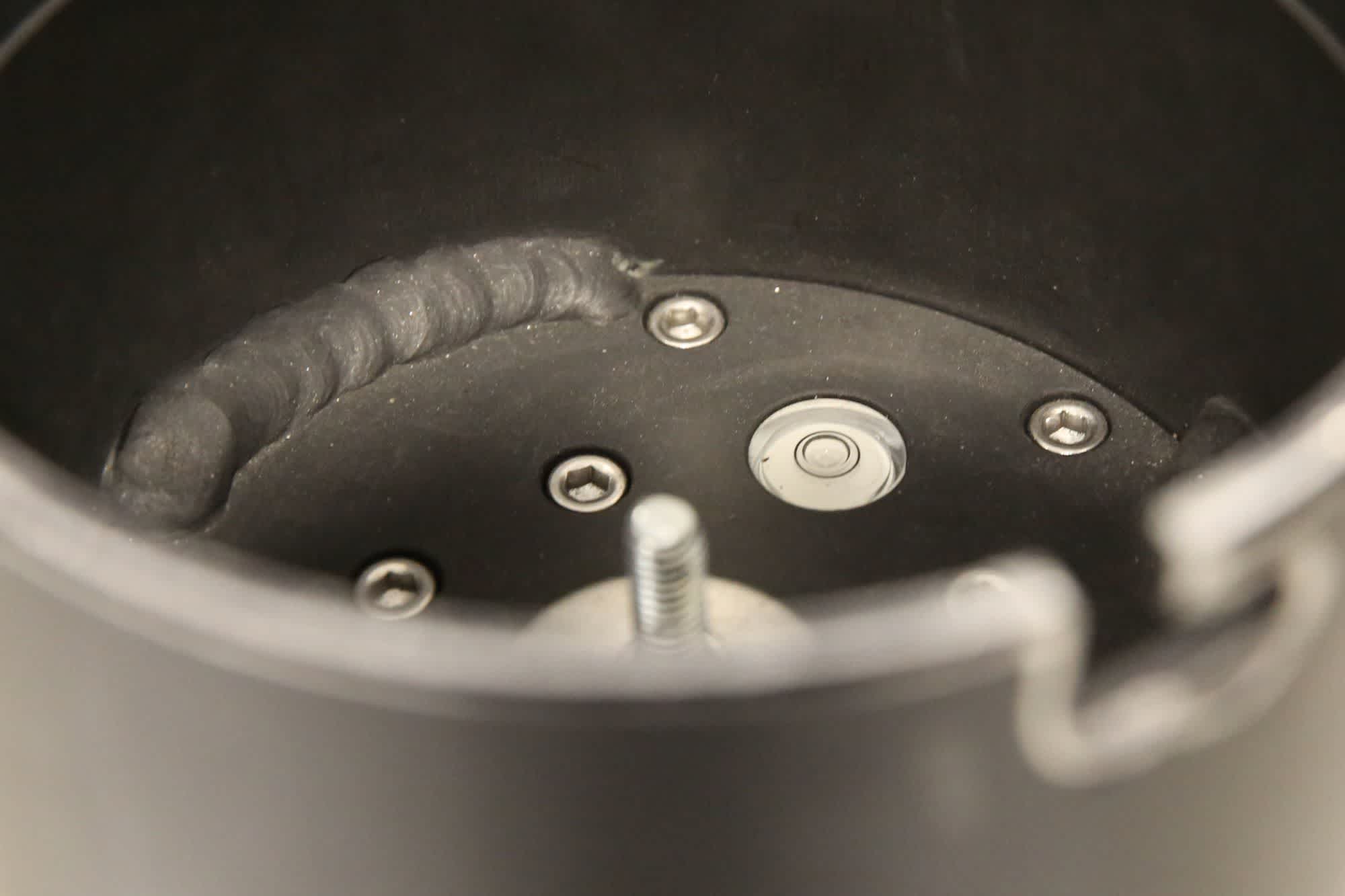
Remove the main centre assembly and drop it into the top of the tripod, aligning the bolts with the cutouts in the side. Twist the assembly slightly to lock it and tighten down the three bolts using the supplied Allen key.
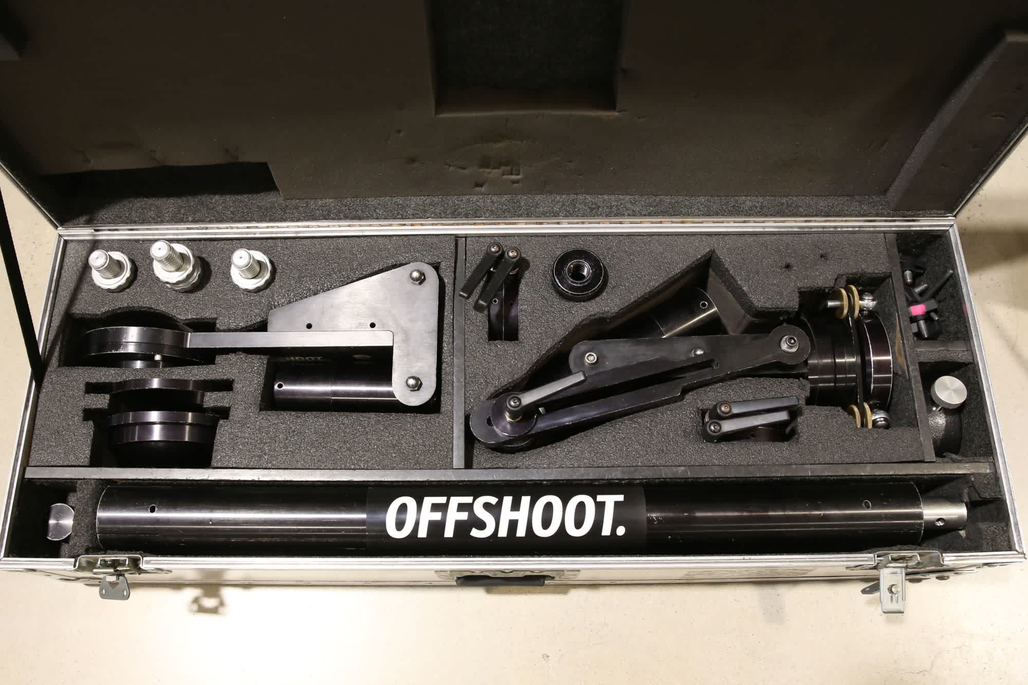
The main assembly of the jib (upper right in the case).
Place the main assembly of the jib into the top of the tripod and twist it. Secure the three bolts to hold the assembly in position.
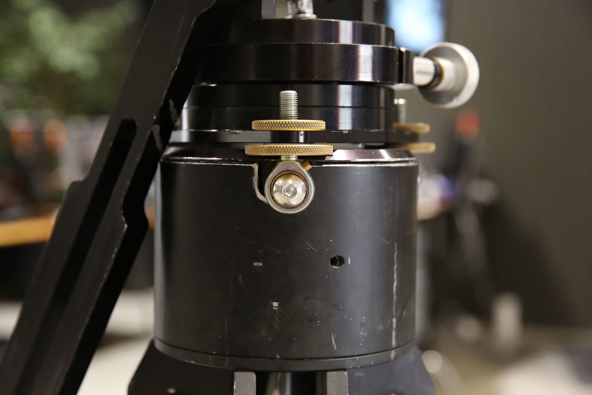
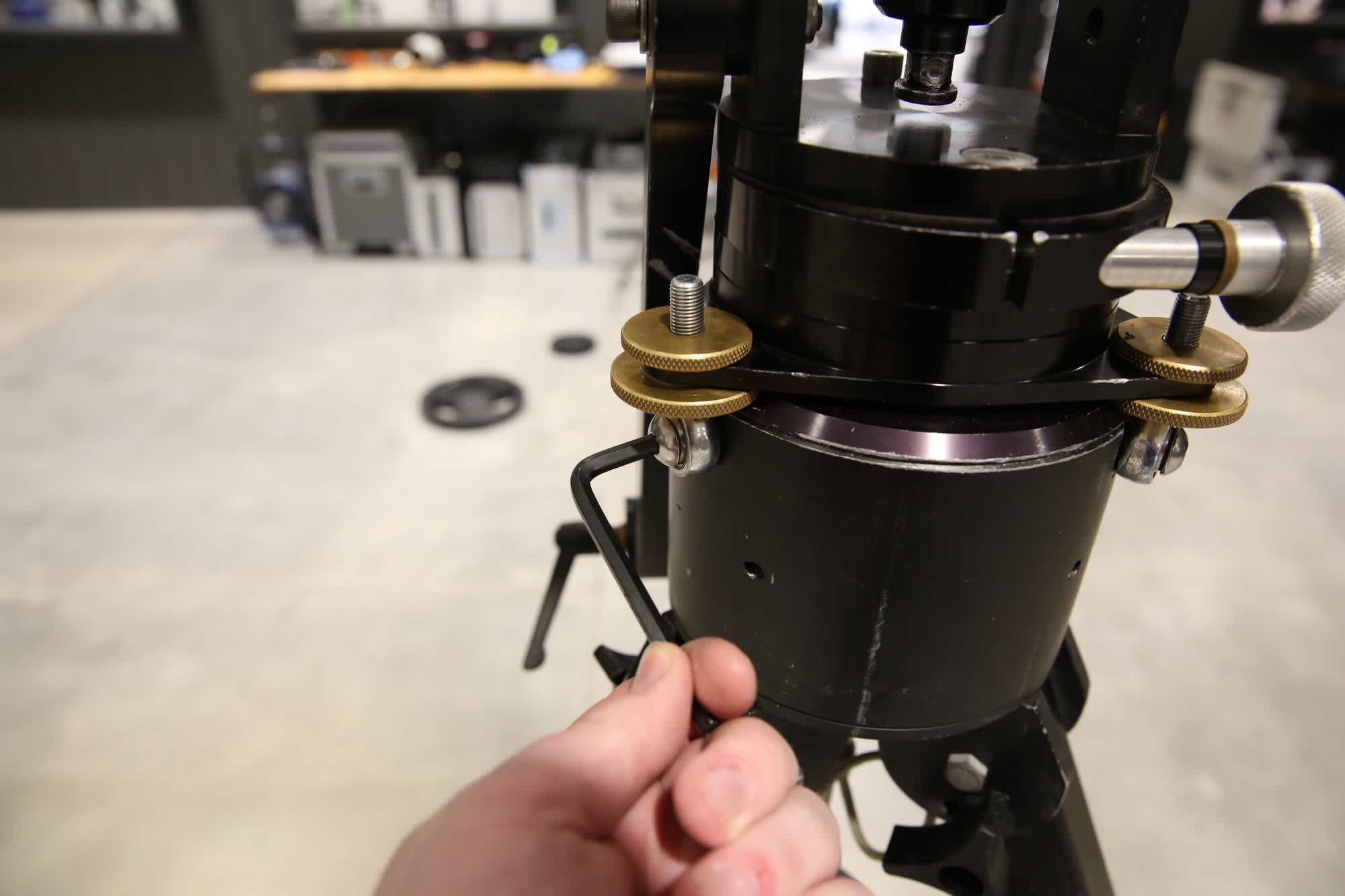
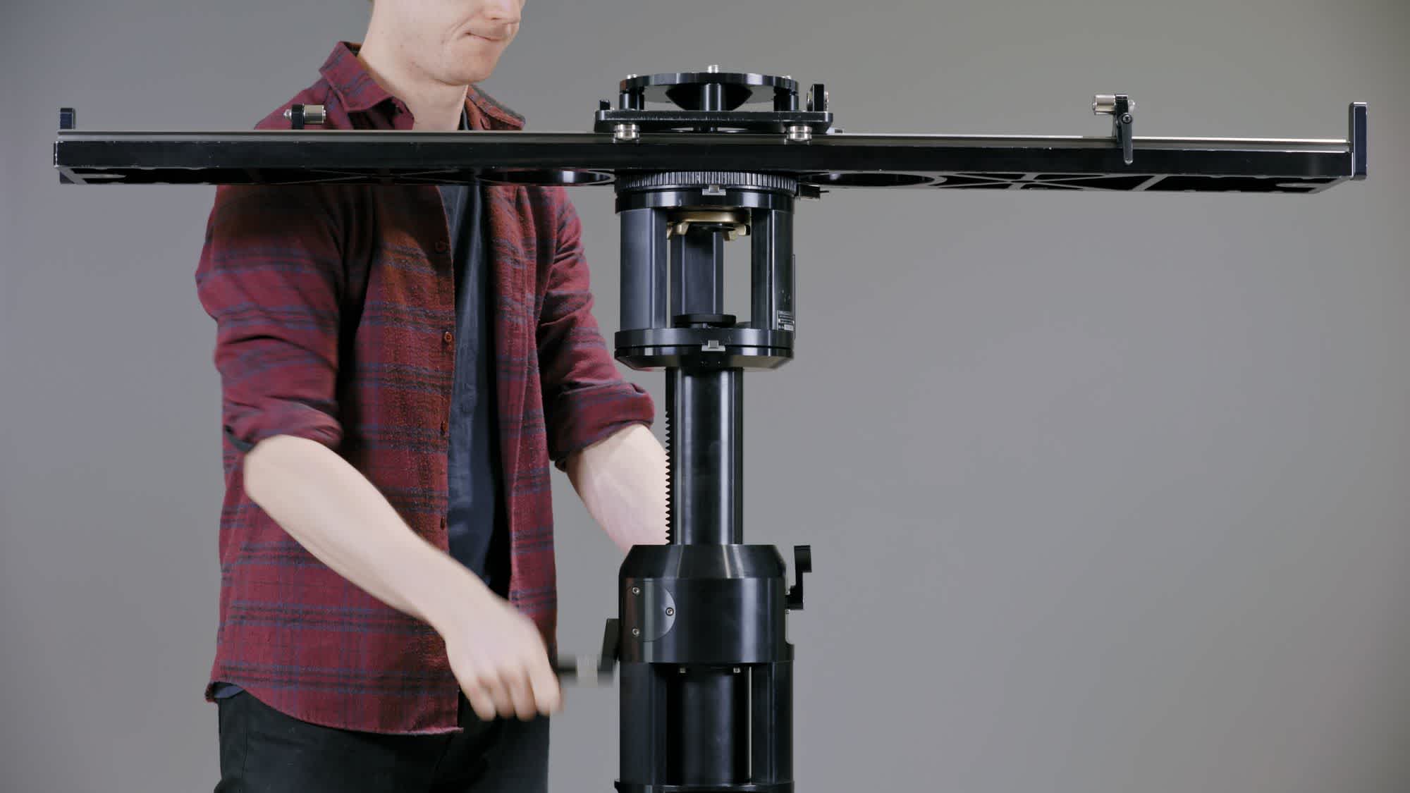
To level the main assembly, loosen the top three brass fasteners and then adjust the three bottom fasteners as required to level the main assembly. Use the bubble level to guide the levelling process - it will tell you in which direction you need to go. Tie down the top fastners when you are done to maintain the levelled position.
Levelling the jib is done via the 3 adjustment points, each consisting of two brass fasteners.
👉 From this point on you need to be careful to not make the jib too heavy on one side, as it could tip over. Make sure you build both sides up at the same time to keep it relatively balanced.
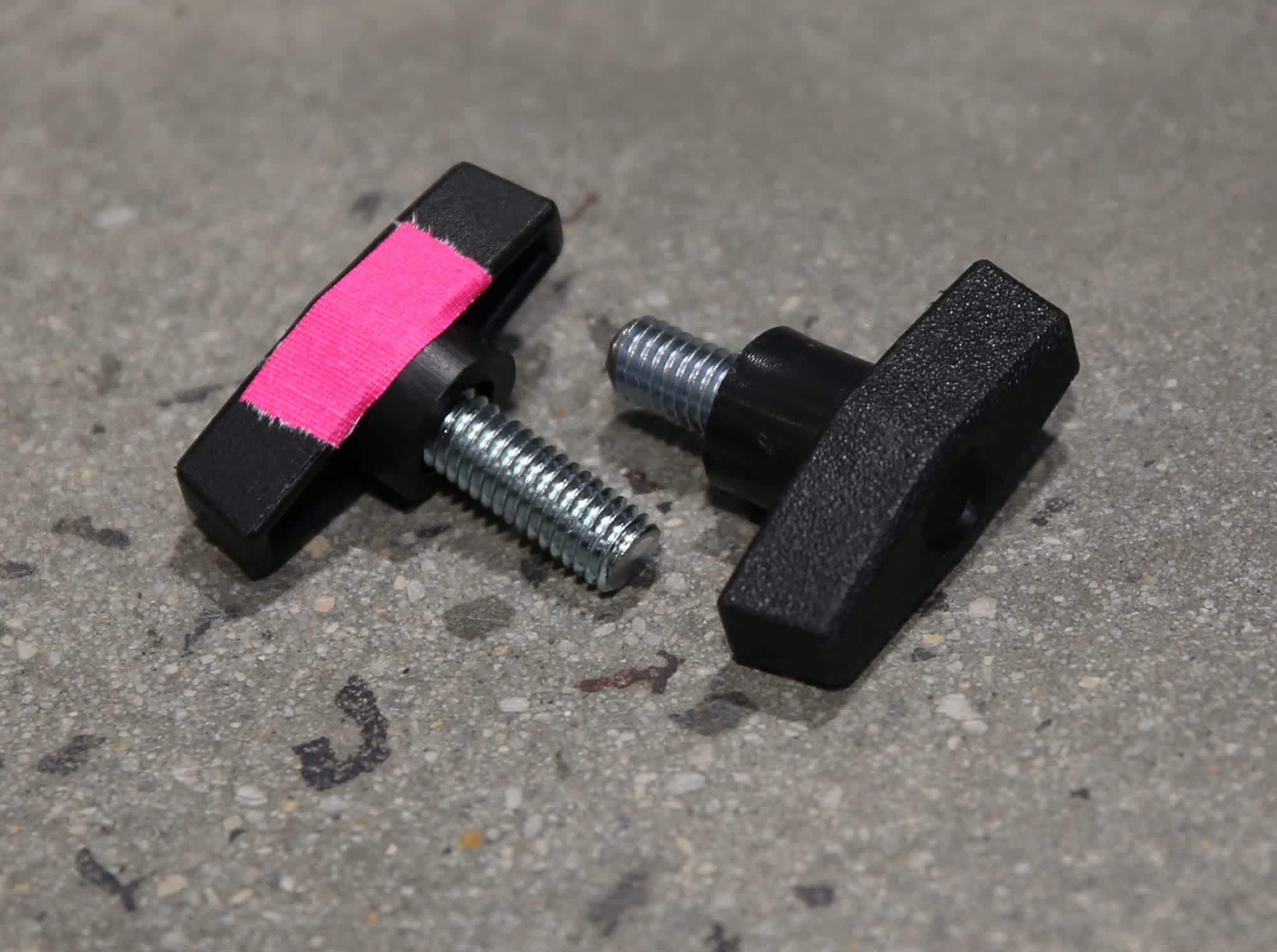
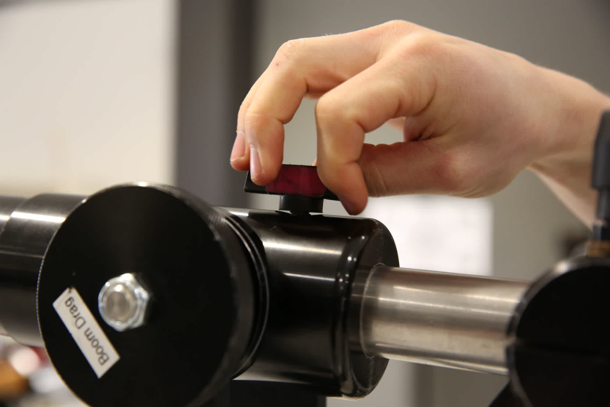
Remove the steel weight bar and the weight bar locking screw from the case. The weight bar locking screw is longer than the other three locking screws. It also has coloured tape on it to help you identify it.
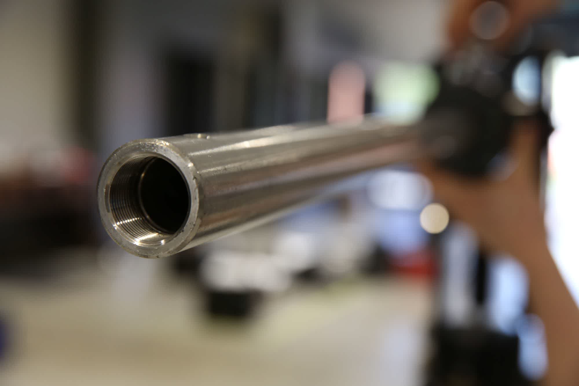
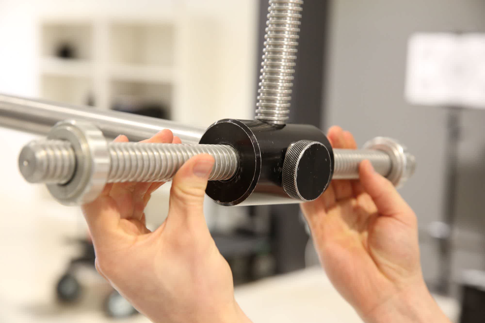
When you look at the weight bar you will see that one end has a thread on the inside, while the other end is smooth. Install the smooth end through the level lock bar and insert it into the back of the main assembly. Use the screw to lock it down through the hole in the top.
The locking tie down to fasten the weight bar is longer than the other tie downs, and will be marked with tape to distinguish it.
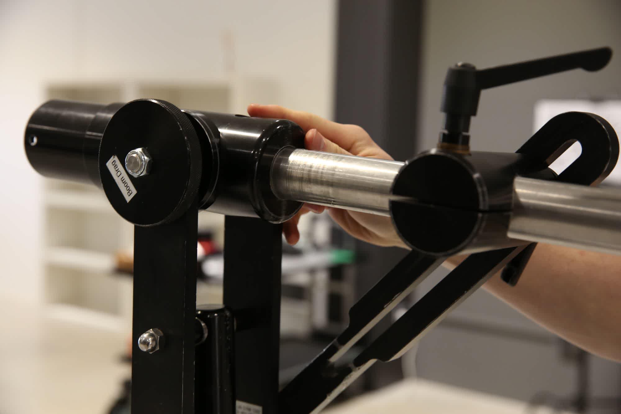
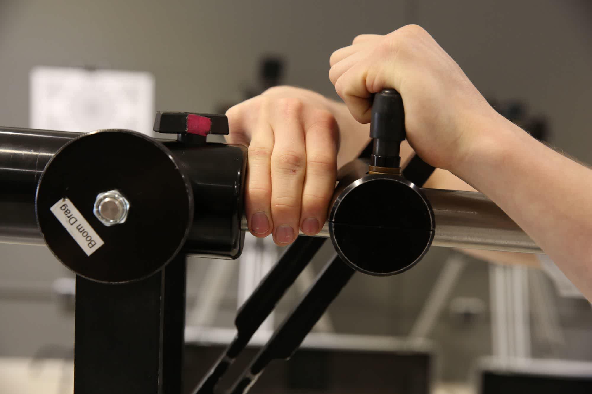
Now position the weight bar so that it is horizontal and move the level lock toward the main assembly. Leaving a 50-60cm gap - which is about the width of 3 fingers - tighten down the clamp onto the bar. Make sure it is fastened tightly as this part shouldn’t move when the jib is being used. Now tighten the level lock to hold the jib in its horizontal position.
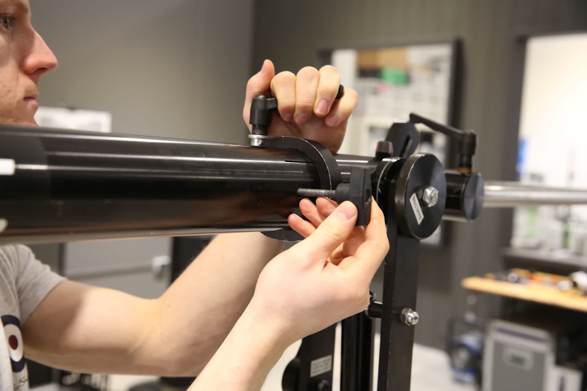
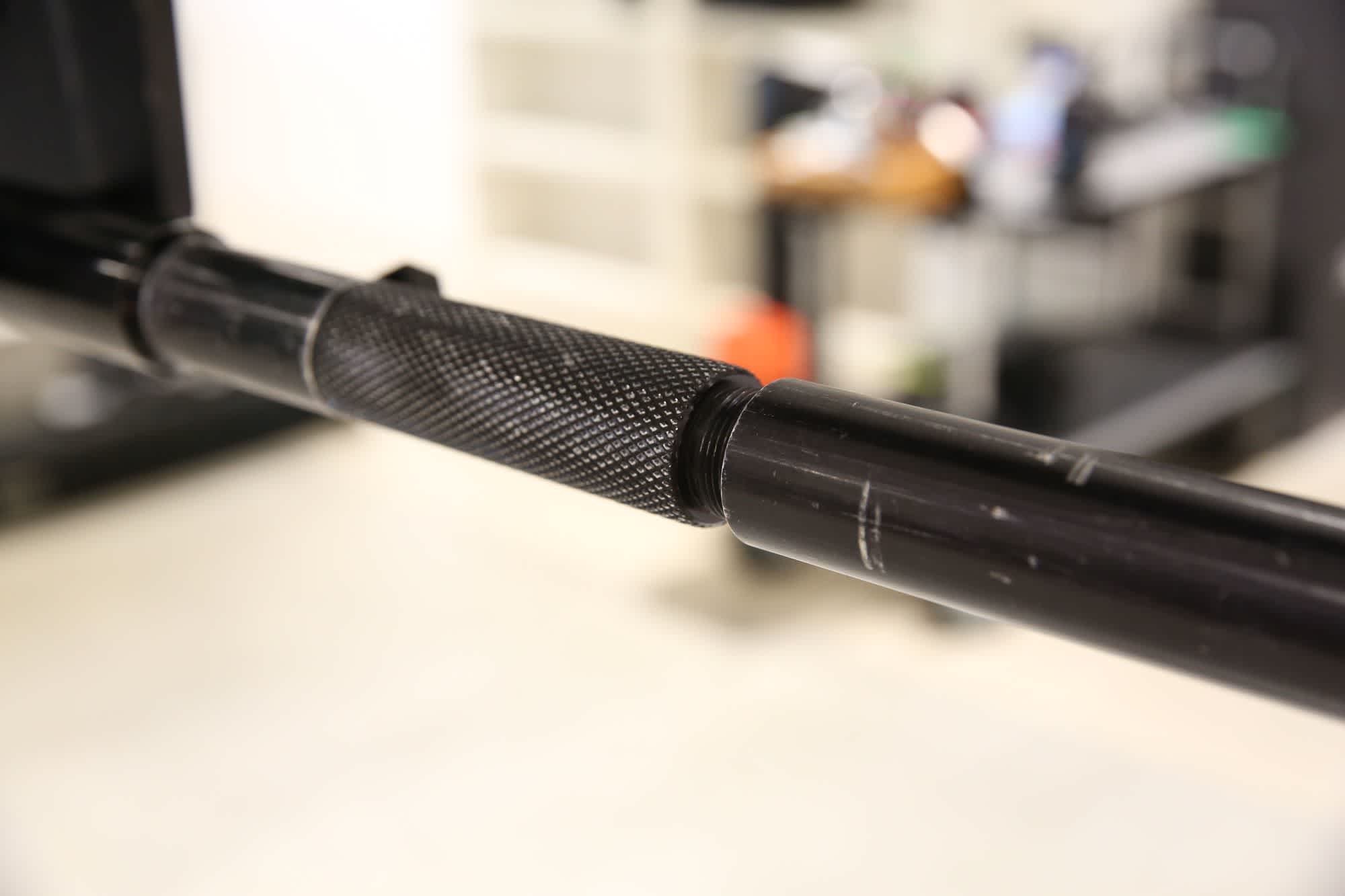
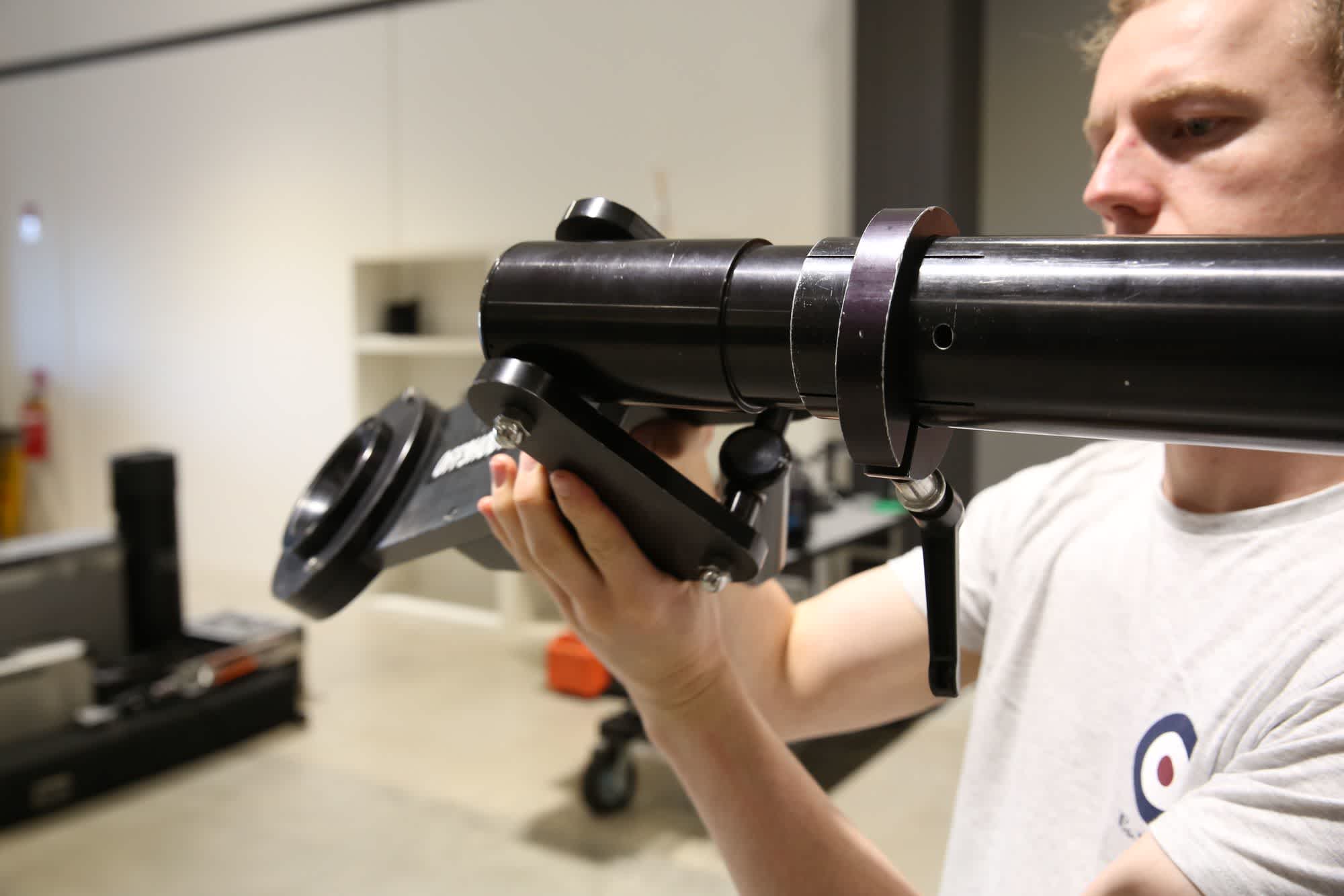
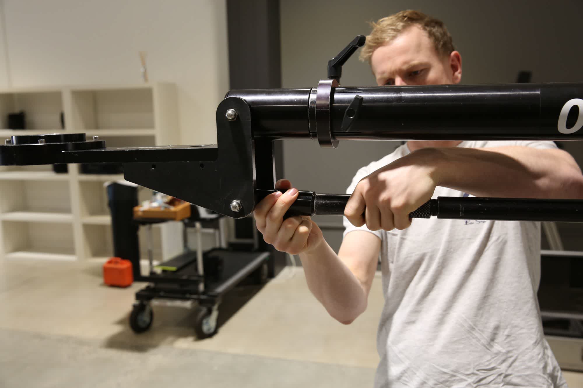
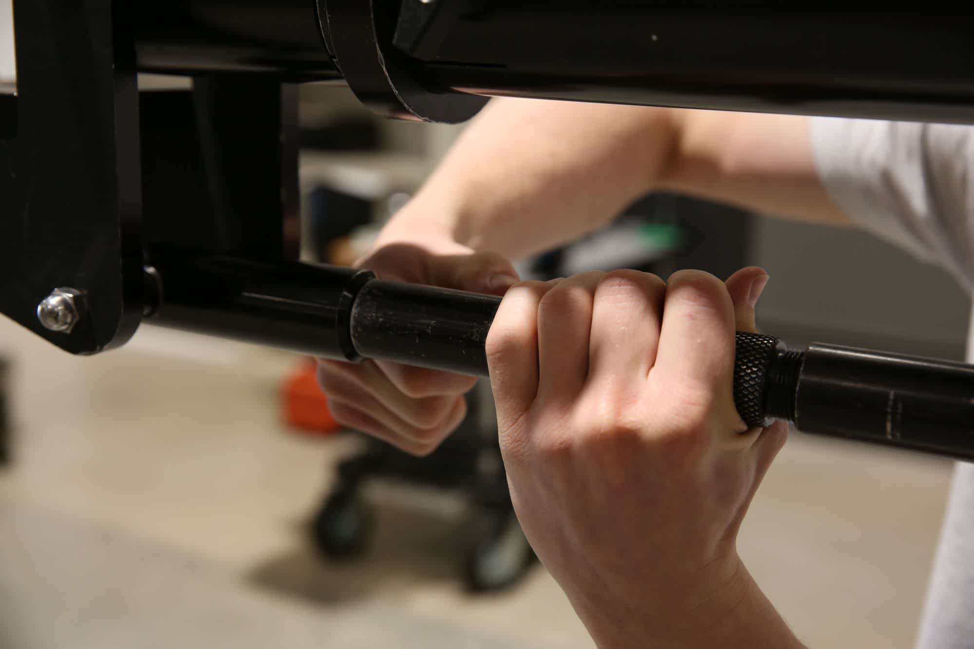
Remove an extension tube, tube clamp and pin from the case. Slide the tube clamp over the end of the main tube and slot the tube onto the front of the main assembly. Install the pin and then tighten down the clamp, ensuring you keep the clamp handle on the top of the jib so it doesn't get pinched during use.
Attach the main tube to the jib assembly with a tube clamp and through-pin.
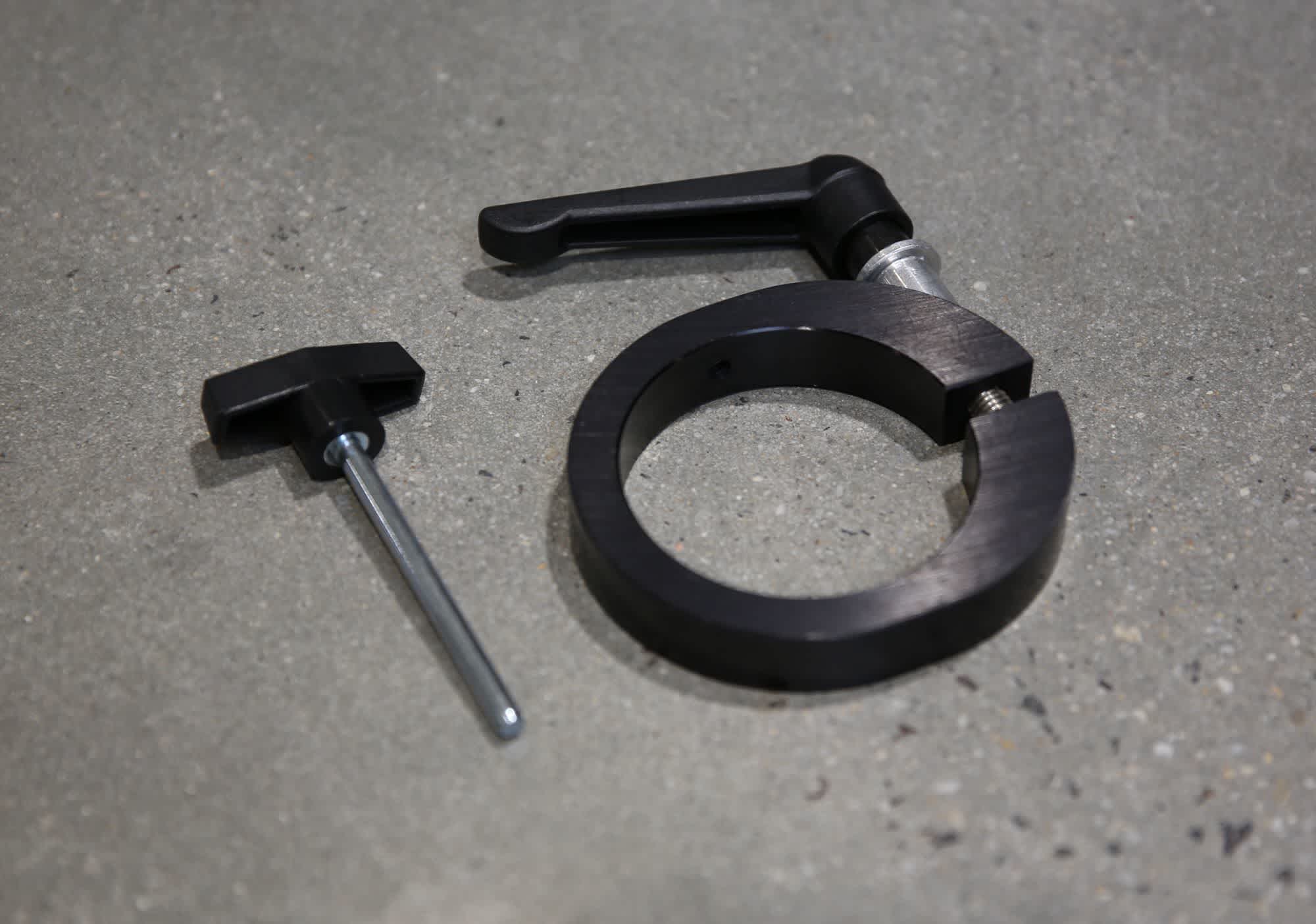
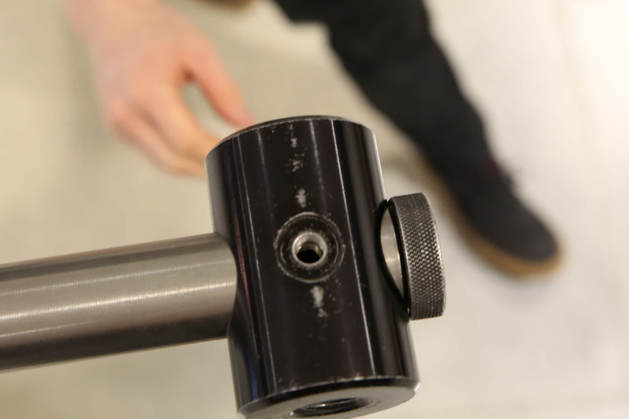
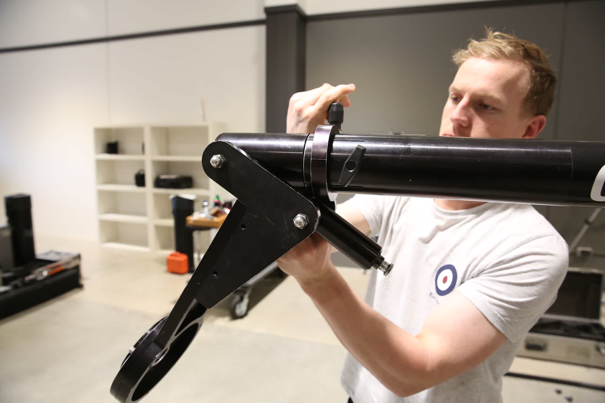
Remove the leveling bar from the case. The leveling bar can be identified by the knurled end that screws in and out to extend the tube. Using one of the 3 small locking screws, attach the leveling bar to the jib, making sure that the head of the locking screw is orientated out to the side of the jib.
Attach the levelling bar to the jib assembly with a tie-down. Make sure the tie-down faces out to one side - not up or down.
Next, take out the sliding counterweight and slide it onto the weight bar. Position it as close as possible to the main assembly.
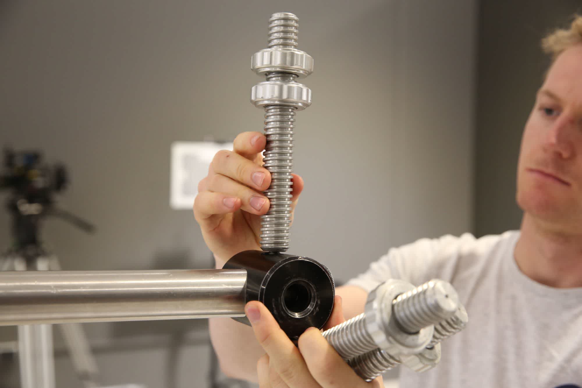
Now install the counterweight bar onto the back using the vector weight bar to secure it in place. Then fit the threaded safety cap on the end. This safety cap will prevent the counterweights sliding off the weight bar should the vector bar thread fail, which would result in the camera crashing to the ground if not supported. 😱
Attach the counterweight bars by screwing the vertical vector weight bar through the threaded counterweight assembly. Thread the two counterweight bars into each side of the counterwight assembly. Be sure to attach the safety cap!
At this point you can install the tube extension if required using the same clamp and pin method. Please note that using the extension reduces the maximum payload of the jib to 20kg.
Now remove the front assembly and a tube clamp, tube pin and locking screw from the case. Slide the tube clamp onto the main tube and slot the front assembly on, securing with a tube pin. Tighten the clamp to secure the front assembly.
The leveling bar can then be attached to the front assembly and secured with a locking screw.
Attach the front assembly with a tube clamp and through-pin. Then attach the front end of the levelling bar to the front assembly.
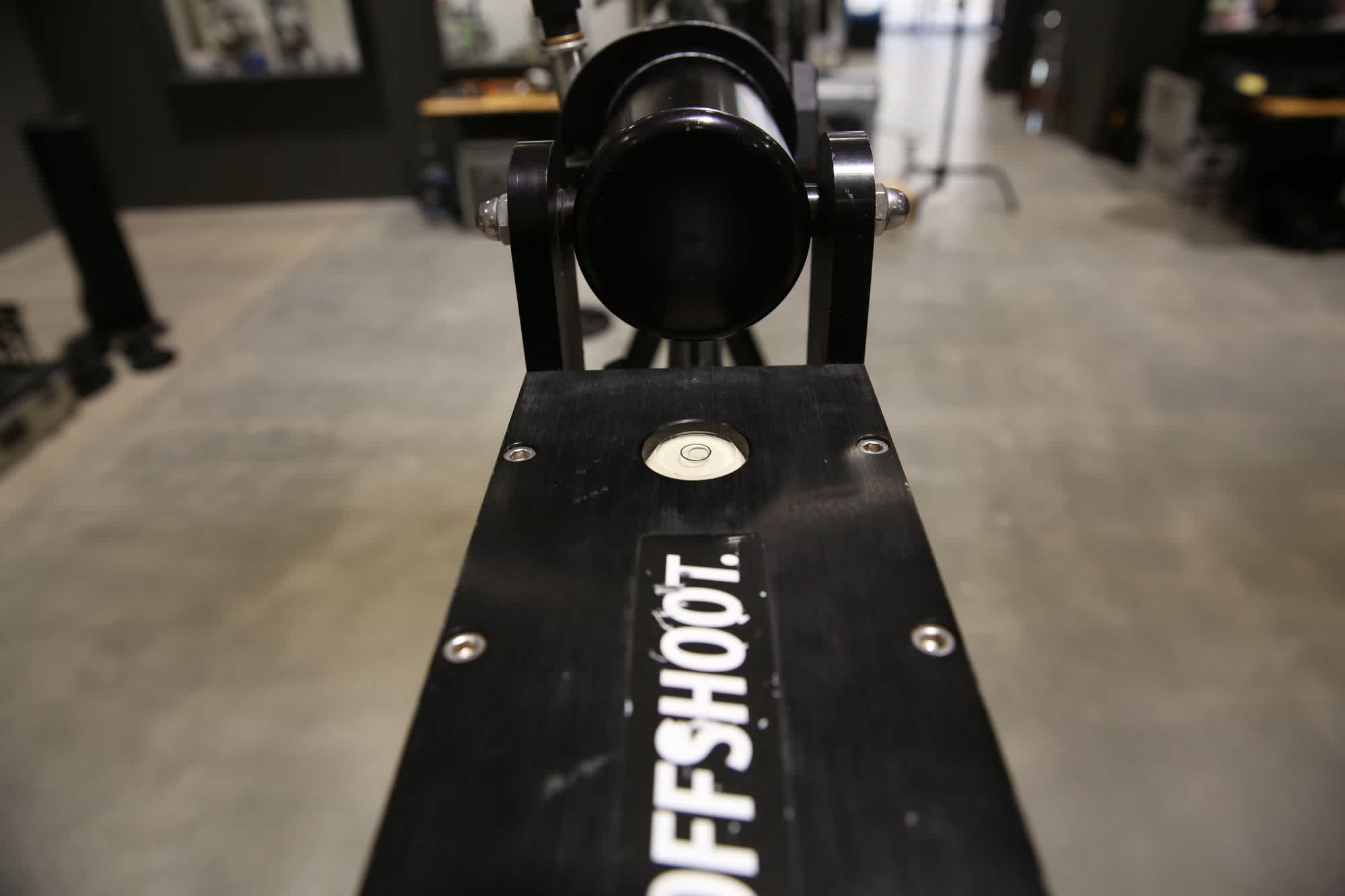
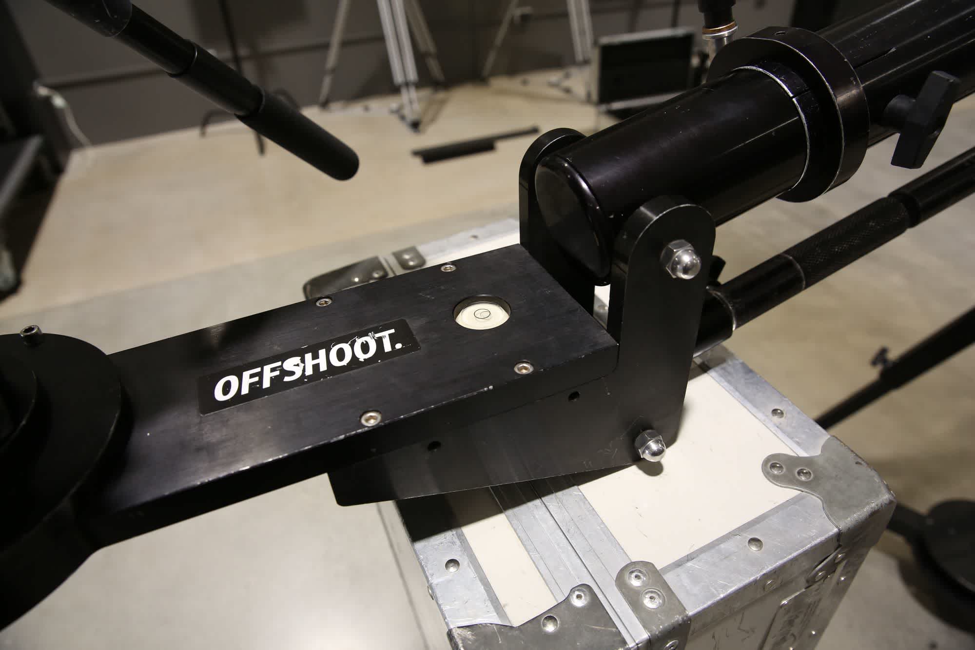
You now need to check that everything is level for a final time. Loosen the tube clamp and rotate the front assembly so that the bubble is in line with the jib arm, then re-tighten the clamps. Loosen the locking screw on the leveling rod and adjust the rod by rotating the knurled end until the bubble is in the center.
Level the front assembly before proceeding.
4. Balance The Jib
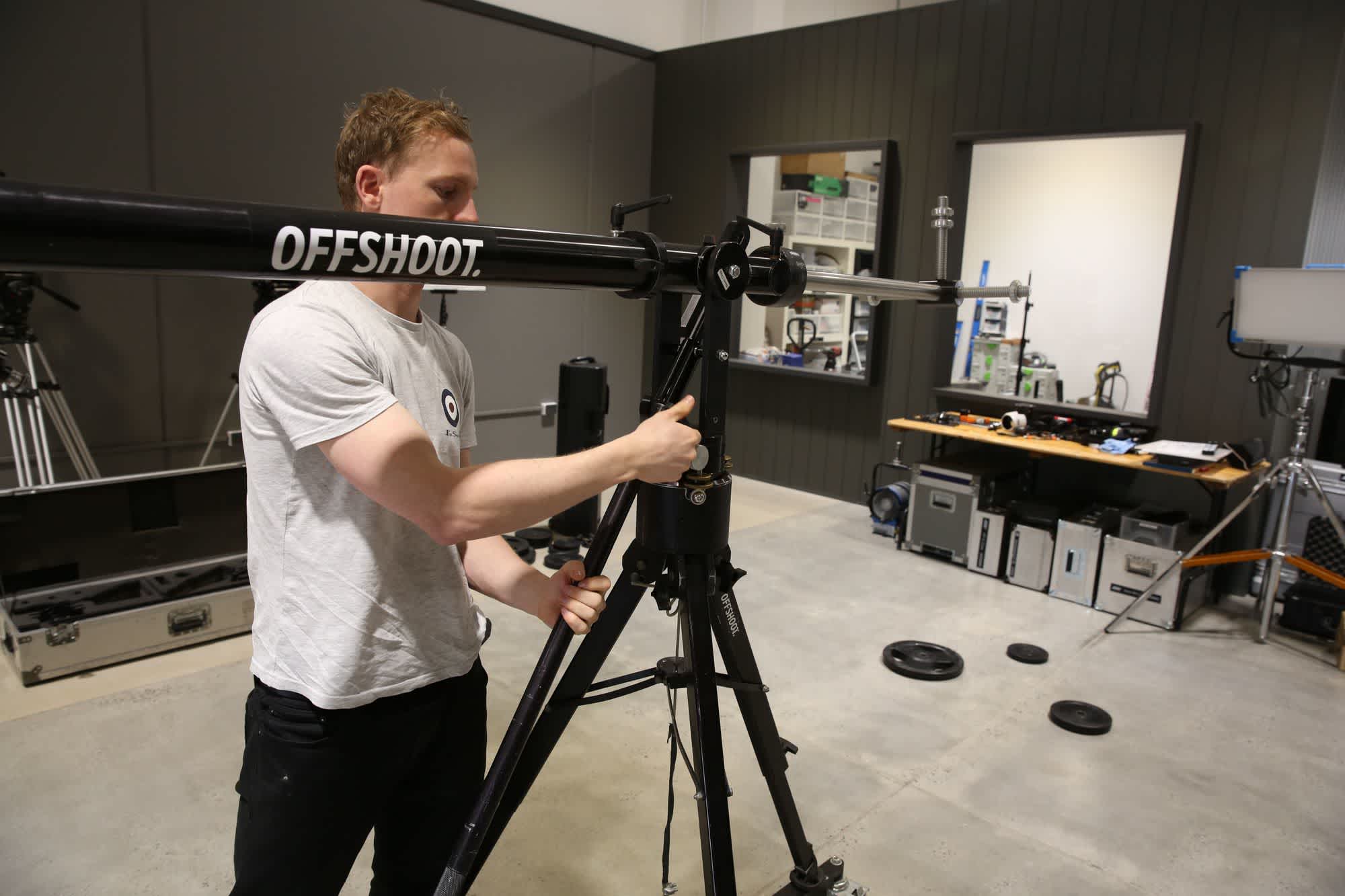
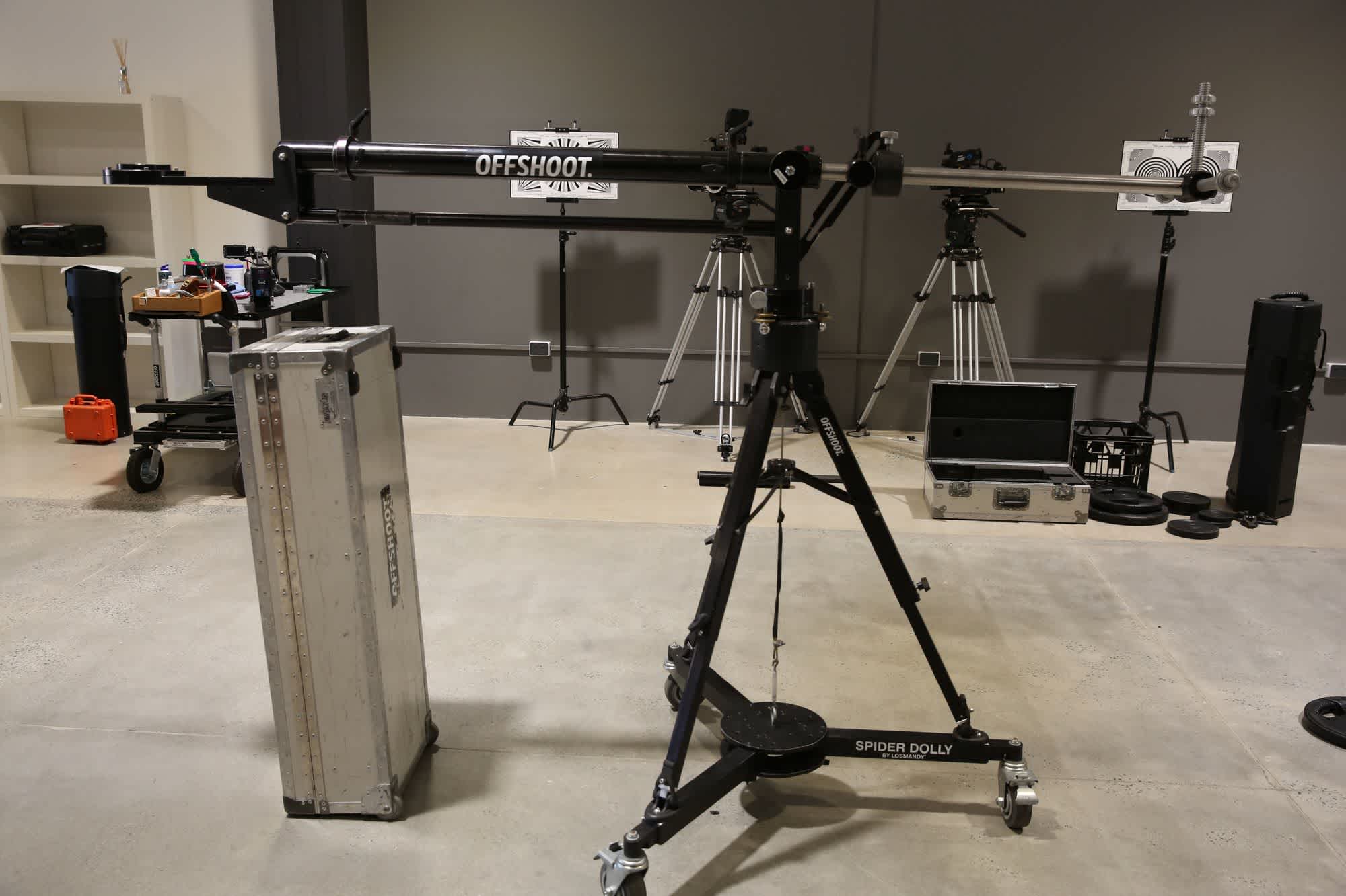
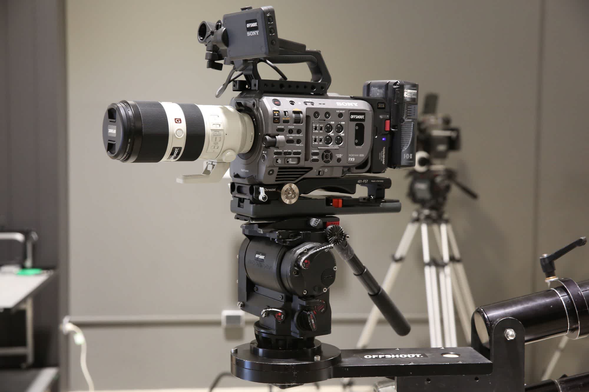
The next step is to balance the jib. Sit the large case up on its end to use as a work platform and then rest the arm of the jib on it. Attach your fluid head and camera to the jib, along with any accessories that will be used on the camera. Carefully release the level lock and ensure the camera is safe resting on the case. Now you can begin putting weights on the weight bar, starting with the heaviest weights.
Support the jib arm with the largest transport case, or a secure bench if you have one. Build the camera up once you know the jib arm is securely supported.
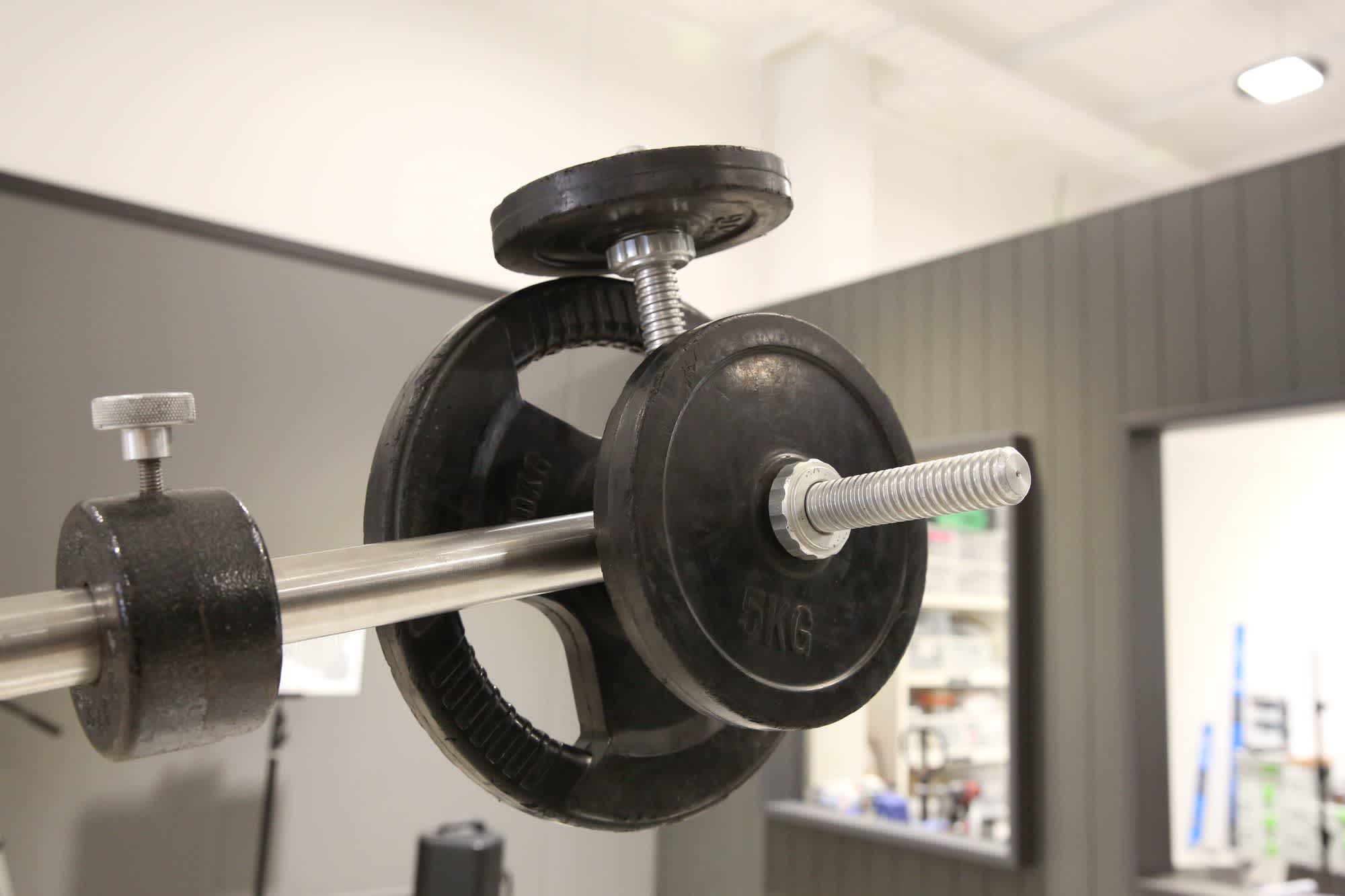
While attaching the weights, make sure you support each weight while it’s being fitted and only release slowly so you can feel if it is going to lift the jib up. If the jib arm begins to lift, switch down to the next size weight. Continue adding weights until the smallest weight causes the arm to lift up. Now secure the weights in place by attaching the 2 locking screws.

The fine adjustment weight (in the left of the frame) is used to fine tune the balance of the jib when the larger counterweights are too heavy to get the final balance right.
Loosen the fine adjustment weight and slowly slide the weight back until it reaches the point that the jib lifts but holds its position vertically. Lock the weight off. The jib is now balanced. 💪 🥇
An optional step is to adjust the vector weight of the jib, which will help with the jib maintaining its position when raised or lowered. If you position the jib at a 45 degree angle, you will likely feel that it naturally wants to drift back to its horizontal position.
You can counteract this by shifting some of the weights to the vector weight bar.
Place weights on the vertical vector weight bar to help the jib maintain its position when it isn't horizontal.
To do this, set the jib arm back down onto the case and shift some of the weights from the side weight arm up onto the vector weight bar. Do not exceed 30% of the weight on this bar. Lock everything off and then move the jib to 45 degrees again and check it holds its position.
Nice job - the jib is now ready to use. 🍻